
Between Two Working Devices — How a Bias Tee Solved Satellite Acquisition Failure
Sometimes an engineering project halts because two perfectly functioning components expect different system architectures. We recently encountered this with a customisation we were incorporating into our system for a long-time client. The setup involved a 5G communication module and an active Global Navigation Satellite System (GNSS) antenna. Although both components were entirely functional on paper, the integrated setup failed to acquire a single satellite signal even under a clear sky.
We paired a Quectel RM520N 5G module with an external GNSS antenna.
The Attention (AT) commands came back clean:
Error 516 means the module cannot establish a position because it lacks data from satellites. We left the setup running to see if it needed time to acquire a signal, but nothing changed. Moving the antenna closer to the window and testing the entire assembly outdoors under open sky produced the same result. The satellite count stayed at zero.
The first instinct in any embedded debugging session is to suspect the configuration. A wrong AT command? A missed initialisation step? Perhaps a firmware version mismatch?
We verified every command against the datasheet and ran the GNSS engine initialisation sequence from scratch. The module remained fully responsive to these serial commands, but continued returning Error 516.
There is a useful distinction between a module that returns errors and a module that consistently returns a specific error. Error 516, 'not fixed now,' indicates that the GNSS engine is running and searching for signals, but has not found a signal to work with. That is a signal path fault rather than a software fault.
Next we looked at the rest of the bench setup. The module was power-cycled (turned off and on again). We tried a different cable. The issue persisted.

Hello. IT. Have you tried turning it off and on again?
Our attention now shifted to the hardware.
The antenna connected to the module was a Quectel YB0027AA, an active GNSS antenna.
A passive antenna is simply a tuned radiating element. It picks up whatever signals arrive and passes them down the cable. It is a simple system that requires no power or preconditions.
An active antenna is different. The YB0027AA has a Low Noise Amplifier (LNA) built into the antenna housing. The GNSS signals arrive at earth's surface at around -130 dBm, which is extremely weak. The LNA boosts those signals by 20–28 dB right at the antenna before any cable loss degrades them. Without that amplification, the receiver only detects noise.
The integrated LNA draws power from the same coaxial cable that carries the RF signal: DC travels up and RF travels down. Inside the antenna, a bias network keeps the two separate.
This raised a new question: Is the 5G module supplying the DC bias required by the antenna?
The hardware design manual had the answer. It stated that the RM520N GNSS interface provides the RF signal path, but does not supply antenna bias voltage. You can connect passive GNSS antennas directly, but active GNSS antennas require an external bias tee.
The issue was clear. Connecting the active antenna directly to the module left the LNA unpowered. An unpowered LNA fails to amplify the incoming satellite signals, keeping them below the receiver's acquisition threshold. The result was:
Both the 5G module and the active GNSS antenna were working exactly as designed. The system simply lacked a bias tee to inject DC bias into the RF coaxial line while preventing the voltage from reaching the module.
We considered three ways to address this issue:
| Option | Advantage | Why Not Selected |
|---|---|---|
| Passive GNSS Antenna | Direct replacement, no bias required | Procurement lead time exceeded one week |
| Commercial Bias Tee | Proven off-the-shelf solution | Procurement lead time exceeded one week |
| In-House Bias Tee | Immediate validation, zero procurement delay | Selected |
With client validation scheduled in ten days, waiting for parts would leave almost no time for integration, testing, and troubleshooting before the demonstration. Therefore, the objective shifted from sourcing new hardware to enabling existing hardware operation within the available schedule.
The bias tee was designed with three primary objectives:
The circuit used two passive components at its core.
DC-blocking capacitor (100 pF, C0G/NP0): Placed in series between the receiver and the antenna junction. At 1575 MHz (GPS L1), a 100 pF capacitor presents roughly 1 Ω impedance, letting the RF signal pass almost unimpeded. For DC, the capacitor acts as an open circuit and protects the receiver's GNSS port from bias voltage.
RF choke or series inductor (100 nH): Connects the DC supply to the antenna-side junction. At 1575 MHz, 100 nH presents around 990 Ω impedance, which entirely isolates RF signal from the supply rail. DC passes through the inductor with near-zero resistance and powers the LNA.
Supporting components included a ferrite bead, 10 µF bulk capacitor, and 100 nF decoupling capacitor. These filter the supply line to keep the injected bias clean and free from high-frequency noise.
We assembled the prototype bias tee circuit by hand onto a standard prototyping board using components available in our lab.
The SMA RF connectors were salvaged from retired Benlycos hardware units. We cut a copper ground plane from a sheet recovered from a decommissioned field device.
The passive components—the 100 pF capacitor and 100 nH inductor—were sourced from the laboratory parts bin. Both are surface-mount devices in an 0402 package, measuring 1.0 mm × 0.5 mm. Hand-placing and soldering components of this footprint requires steady manual positioning, a fine-tip iron, and high-intensity illumination to prevent component drift or unintended solder bridging across neighbouring pads.

The rapid-prototype bias tee circuit assembled by hand on a prototyping board
Connecting an unverified, hand-built circuit to an RF module introduces risk. A potential DC fault on the RF line would apply bias voltage directly to the GNSS input, causing hardware damages and timeline resets.
The assembled bias tee had to pass four checks:
| Check | Expected Result | Outcome |
|---|---|---|
| DC IN → RF+DC OUT (centre conductor) | Continuity through the choke | Pass |
| RF IN (centre conductor) → Ground | 0 V — capacitor blocking DC | Pass |
| RF+DC OUT (centre conductor) → Ground | Full supply voltage present | Pass |
| All connector shells | Common ground confirmed | Pass |
The results from the multimeter indicated that DC reached the antenna port and remained isolated from the module port. Only then did we connect the RM520N and move the setup outdoors for open-sky validation.
The AT commands that had returned nothing for days came back this time with real data.
AT+QGPSGNMEA="GSV" reported 12 satellites in view, with signal-to-noise ratios of 45, 47, 38, 43, 35, 47, and 48 dB-Hz. Readings at 40 dB-Hz and above indicate excellent GNSS reception, confirming the prototype circuit introduced negligible signal loss.
The receiver resolved a clean position fix within minutes:
Decoded:
Outdoor validation confirmed successful GNSS operation. The receiver acquired 12 satellites with 35–48 dB-Hz carrier-to-noise ratios and successfully returned latitude, longitude, and altitude. These measurements confirmed that the externally built bias tee correctly powered the active antenna while preserving RF signal integrity.
| Parameter | Result |
|---|---|
| GNSS Fix | Successful |
| Satellites in view | 12 |
| C/N₀ | 35–48 dB-Hz |
| Position | Latitude, Longitude |
| Altitude | 907.6 metres |
The successful validation enabled the customer demonstration to proceed on schedule at zero material cost and zero procurement delay.
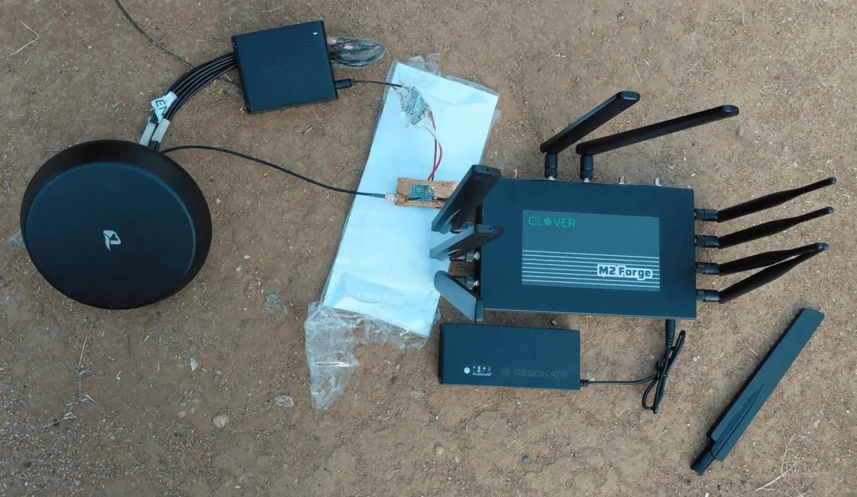
Open-sky field validation setup featuring the modified circuit
This fault illustrates something that comes up repeatedly in embedded hardware work: A peripheral that initialises correctly in software is not always supported end-to-end electrically. The GNSS engine was healthy at every stage of the investigation. The failure oversight occurred one layer below the software, in the RF and power path, rendering it invisible via AT commands alone.
It also demonstrates a practical principle for small teams facing tight deadlines: Diagnosing the underlying circuit requirements could allow you to build a workaround faster than commercial procurement logistics. A bias tee is electronics we learn in textbooks. Once the root cause was clear, the path to a working solution was just an afternoon of bench work.
We have added the last lesson to our hardware bring-up checklist: Before raising a purchase order, check what is already available. The connectors and ground plane recovered from decommissioned hardware became the exact materials needed to validate a live product feature.
Note: The Bias Tee was built as a rapid engineering prototype for laboratory validation within the project timeline.
Our team specializes in rapid prototyping and embedded systems engineering for mission-critical connectivity.
Get in Touch